PCBPT
Liu, F. and Paradiso, J.A., 2023, October. Printed Circuit Board (PCB) Probe Tester (PCBPT)-a Compact Desktop System that Helps with Automatic PCB Debugging. In Adjunct Proceedings of the 36th Annual ACM Symposium on User Interface Software and Technology (pp. 1-3). [PDF]
Top 100 Entry in the Create the Future 2023 Design Contest (Link) (Certificate)
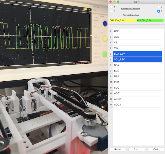
With PCBPT, all you need to do for PCB debugging are choosing the signals you want in schematic and checking the output when you are debugging a PCB like this:.
Manual probing is the primary approach for debugging PCBs. However, our hands may not be precise and stable enough to accurately place the probes on pads without short circuiting adjacent pins, which will cause more problems. On the other hand, if multiple signals need to be tested, our hands may not be enough. We could also use probe hook clips. However, this often requires extension wires that are soldered on the targeting pads.
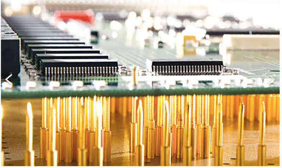
Another approach is using a bed-of-nails jig. To use the bed-of-nails, a jig needs to be designed and made to install all pins. But every jig is for only a single particular PCB design. Even a tiny change of a single pin position requires designing and making a new jig, which is poor time effective.
Flying probe tester is also an option. It is precise and fast and can provide efficient diagnostics for different PCB designs. However, commercial flying probe tester products are very expensive and massive, which are not suitable for hobbyists and small companies.
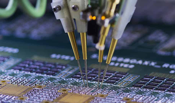
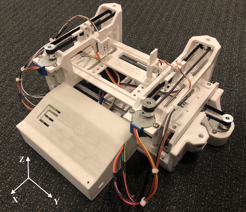
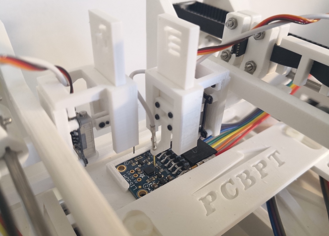
Here we present the PCB Probe Tester (PCBPT), a PCB automatic probing tool that helps with your debugging. It's composed of a miniature probing machine you can put on your desk and a control program run in PC. The program will parse the board design file created in Eagle, and list all the signals you can measure in the design. After you choose the signals you want to measure, the program will choose the proper pads (according to size, and if the pads are ICs pads) for the signals and calculate their coordinates, then the machine will place the probes on the pads selected. This is a new way for the hardware designers to interact with their designs.